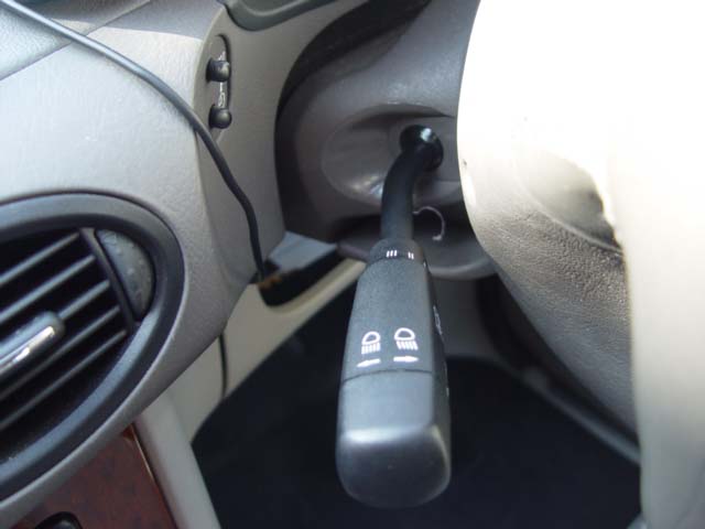
 The combination switch Part number W168 545 01 107 D88 on all models, is possibly one of the most used components on the car . As it is name implies it combines and carries out a number of functions being controlled by the driver and when it goes defective cause all manner of problems.
Do remember that if you are replacing the combination switch the battery Must be disconnected If you fail to do this the SRS warning light will show when you next turn on the ignition. Some OBD/EOBD diagnostics tools will re-set the SRS so follow the rule and and save yourself the cost and inconveinience of getting a garage to re-set the SRS.
Merecedes Benz may even refuse to re-set the SRS without first checking the work which has been done DIY.
The same rule applies to any component fitted with an Air bag. Passenger side dash, drivers and passenger doors where air bags are fitted
Comments have been made that Garges do not disconnect the battery! Reason, they have diagnostics tools which can re-set the SRS which is quicker than reconnecting the battery, re-setting the ESP/ABS and electric windows.
Items controlled by this switch include:-
Indicators (Direction Of travel indicators)
Windscreen wipers, 3 variable speeds and off
Front Windscreen washer, (Electric)
Headlight main beam /dip switch control. Head light flasher.
Head light flasher The head lights of the car will light when the switch is held towards you with the ignition ON. No other lights show Front or rear.
The head lights will remain on for as long as the switch is held, switch returns to off position when switch lever is released.
Note This facility is generally used to indicate to other drivers that you are giving way, to allow them to exit access junctions etc, On motor ways generally used to indicate to drivers of long/large HGV vehicles that there vehicle is passed you and that you are prepared for them to pull back into the lane in front of you.
Although both of the above are used extensively by drivers I'm not aware that they are in the official highway code. So if you are using these methods to indicate to other road users or indeed acting on this form of signaling always treat them with caution and expect the unexpected! (always treat them with caution)
Drivers will I'm also have seen this facility being used when dangerous maneuvers are undertaken by drivers, vehicle coming towards you overtaking causing you to brake or take evasive action, again this is not an official warning and may cause confusion so be aware.
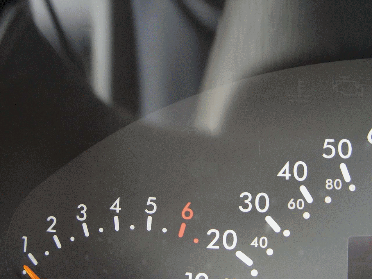
Main beam /headlight switch.
With Main lighting switch turned to ON/headlights.
The main /dipped beam facility/switch is operated by pushing the combination switch arm/lever away from you which will allow main/full beam lights to be lit.
The blue full beam indicator symbol as seen in the photo, will display in the instrument cluster when main beam is selected
Pull/flick the switch towards you and the lights will revert to dipped beam, main beam indicator goes out, no symbol is displayed.
Indicators
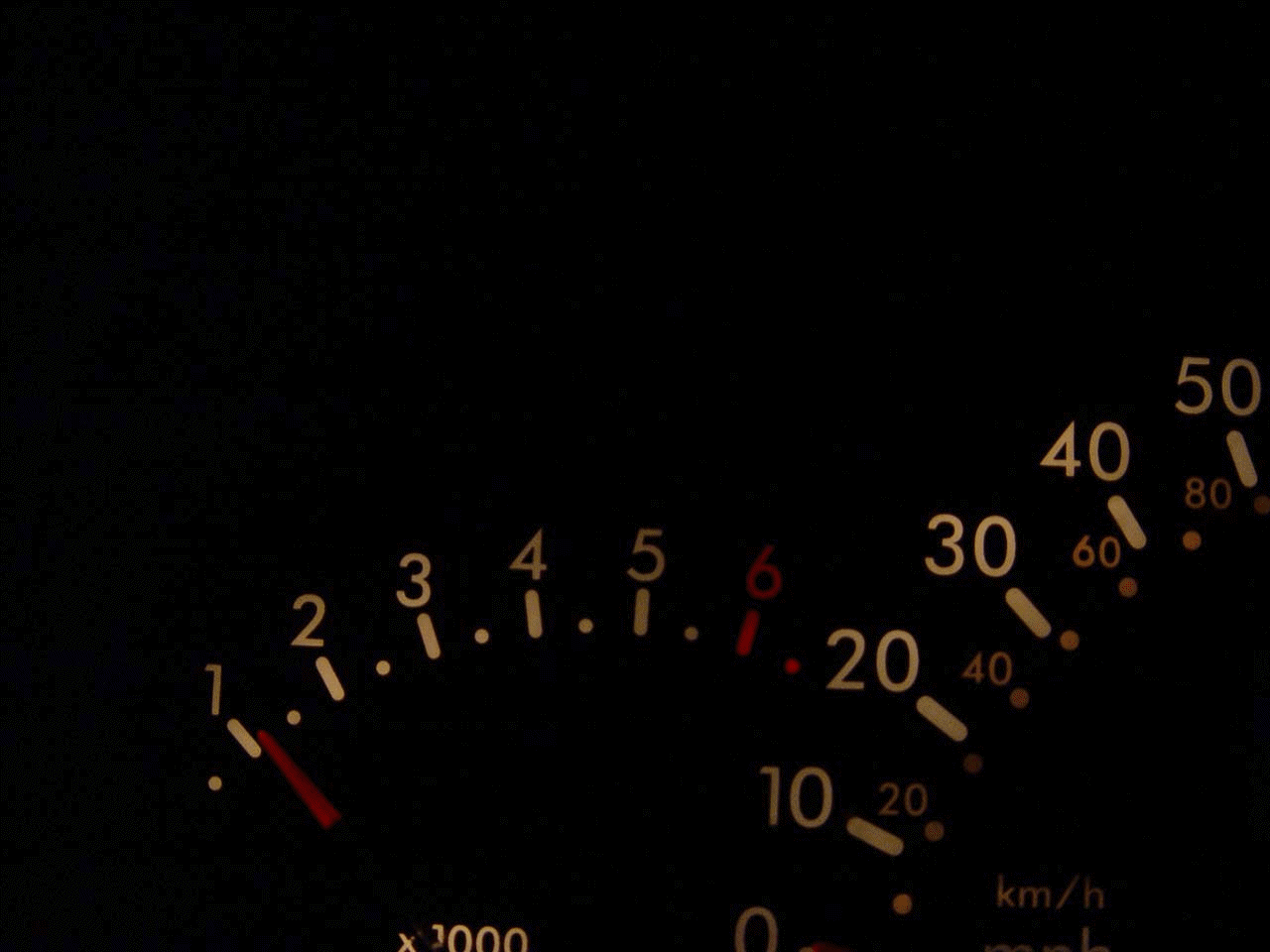
The indicator warning signal in the instrument cluster will flash at approximately the same rate as the human heart 72 beats per minute, in fact its slightly more at between 75 & 80 flashes per minute. The flashing being accompanied by a clicking sound. as well as the intermittent lighting of 4 main bulbs front & rear plus 2 repeater lamps situated in the front wings
The indicator flashing in the photo indicates we are about the turn left.
Both green indicator arrows illuminate when the hazard warning switch is pressed. The indicators are self canceling. Having turned left or right the movement of the steering wheel will cancel the signal being given as it is re-centralised.
However attention should always be paid when operating the indicators to ensure they do cancel. If changing lanes on motorways for instance, the degree of movement of the steering wheel is not always sufficient to cancel the indicators, it is therefore necessary to cancel them manually.
Blown bulbs
The Speed of the flashing will be affected when bulbs blow :- If a repeater lamp bulb situated in the wings blows the speed of the flashers remain the same.
However if a main lamp front or rear blows the flashers speed increase dramatically so there is no excuse for driving with indicators that are not working correctly and in all cases the bulbs for the indicators can be replaced in minutes, providing of course you carry spares , which if your going abroad you are obliged by law to do.
I carry a complete set in the cubby in the boot area and they take up very little space. Remember you do need amber coloured bulbs on the 2001 onwards 'A' Class as the lenses are white.
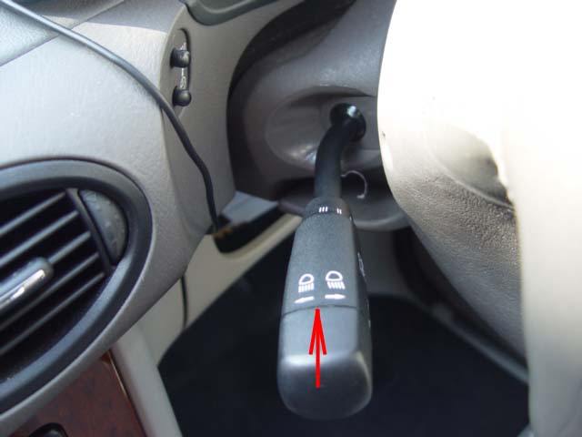
Front Windscreen wash facility
The electric pump situated in the lower side of the windscreen wash fluid reservoir is operated by pushing the combination switch lever arm in towards the steering column. The action of the windscreen wipers and washer fluid is automatic as the lever is pressed the washer will spray the screen, wipers will make two complete sweeps of the screen and the automatically stop. if further washes as required the procedure is repeated.
It is worth knowing that the front washers nozzles on the 'A' class are heated and so so the problem of blocked nozzles due to icing should be illuminated.
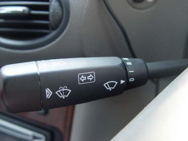
Front Windscreen Wipers.
The windscreen wipers are controlled by the combination switch by turning the lever arm away from you, the driver, (Anti-Clockwise) Four setting:-
position.
O = Off
1= 1 x Intermediate sweep approx every 5-7 seconds (17-20 sweeps per minute)
2 = Standard speed approx 45-50 sweeps per minute.
3 = Fast 75-80 sweeps per minute.(These figures are on a wet screen)
Problems associated with the combination switch
Please Note
On sevearl occasions over the last 10 years or so Owners have contacted me with a problem where the indicator switch fails to produce the correct signal, although I have mailed owners I have never been able to add the information due to lack of feed back . However Tony has just suffered the problem and has provided the answer I will post his mail here:-
The issue is when you put the indicator stalk in the LEFT position and the dash indicates RIGHT as well as the actual right hand indicators front and rear of the car. There is no problem when indicating right. The issue occurs 90% of the time (in other words i cannot be trusted!) I initially tried replacing the indicator stalk as this seemed to be an obvious place for the problem to be occurring (with no luck). I have since replaced the instrument cluster with immediate success! So the fault does originate from the instrument cluster. All references to this that I have found state that it is not repairable and a replacement cluster is the only remedy. Thank you Tony I'm sure this will help owners with this problem which I should add is rare.
Other defects
Dip switch fails to dip main beam.
Flashing facility does not work.
Main beam lighting comes on when light switch is in the off position.
When the light switch is in the full beam position, dip switch fails to operate. High beam blue symbol remain on in the instrument cluster.
Broken lever
Indicators fail to operate correctly.
Windscreen wipers cannot be controlled, in one instance could not be stopped without turning off the ignition.
Pulling fuse 9 or 11 may resolve the problem, but it will effect other services so check before moving the car further.
Remember failure of this switch can be either mechanical or electrical, to change the switch necessitates removing the :-
Drivers Airbag,
Steering wheel,
and clock-spring,
which is possible DIY providing you have the skills and good selection of high quality tools.
Before attempting this task disconnect the battery to isolate the drivers airbag.
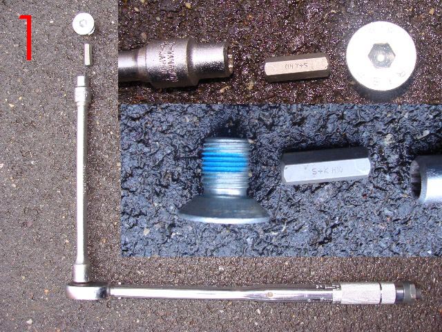
If you do decide to tackle this job then you will need:-
1. Torque wrench (for leverage and correctly tightening the steering wheel securing screw)
2. 10"-12" 1/2 Extension bar
3. 10mm socket
4. 10mm Hexagonal bit (the steering wheel is secured with a 10mm wedge headed screw.)
5. Phillips screw driver fine and medium
6. 1 x T25-30mm 'Torx' bit approx 3" (75mm) in length, or a 'Torx' holder with a shaft no greater than 8mm in Dia.
7. Small wrench and suitable socket to hold bit.
8. Lock-tight for re-securing the steering wheel locking screw.
9. Small pen magnet for removing and returning the screws from combination switch recess holes.
10. 1 pair of pointed nose pliers
PREVENT ACCIDENTS
* When ever the need arises to remove the steering wheel or associated components it is necessary to Disconnect the Battery there is an air bag situated within the steering wheel assembly which if accidentally activated by short circuiting the contacts could cause serious/fatal injury.
REMEMBER there is a specific procedures set down on my page 13 and page 300 in your Mercedes-Benz handbook for disconnecting the battery
Disconnecting = Negative terminal first
Re-connecting = Positive terminal first
Preparatory action prior to Removal of Steering Wheel.
1. Record /check availability of radio code as appropriate
2. Place keys in ignition,
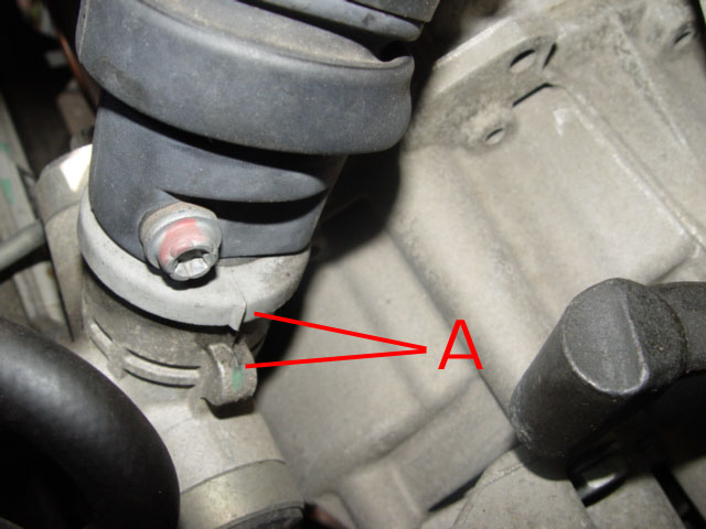 3. Align the road wheels as straight ahead. See markers on lower steering column components. A
 4. Remove the keys from the ignition and move the steering wheel slightly in either direction until the steering lock engages.
5. Chock at least one front wheel both front and rear, this will assist in maintaining the identical wheel alignment/position of the steering. This action is vital as the steering wheel MUST be replaced in an identical position as removed
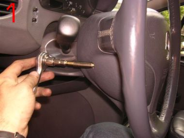
6. Removing the steering wheel, the securing screw will be very tight, I found I had to use my torque wrench to get the leverage to undo this screw.
Replacing the steering wheel even one spline from it is original position can cause the deactivation of the direction indicator mechanism to fail as well as bring up the ESP/ABS light when re-assembled.
Look for the larger gap in the spline (Teeth ) of the column, if there is no markers ensure you introduce one before removing the steering wheel. The very small black line is the MB marker I also marked with white paint.
7. Disconnect the battery and secure the terminals to prevent them accidentally contacting the battery posts.
Disconnecting = Negative terminal first
PLEASE NOTE
Having disconnected the battery and removed the Drivers Air Bag DO NOT RECONNECT power until it has been refitted.
If you turn on the Ignition on without the Air bag connected you will get a SRS (Safety Restraint Systems)fault lamp light on the instrument cluster, the fault having be stored in the memory of the ECU, this cannot be deleted and hence the lamp turned off without visiting a MB workshop or MB independent garage where the fault code will need to be deleted using diagnostics equipment. This action will automatically delete the lamp.
Some of the more sophisticated EOBD hand held Diagnostics tools do now (08/2010) include this feature, so ask around before paying £50,00 plus which is what your likely to be charged by Mercedes-Benz Workshops. *Note
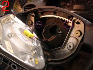
 Removing the Steering Wheel
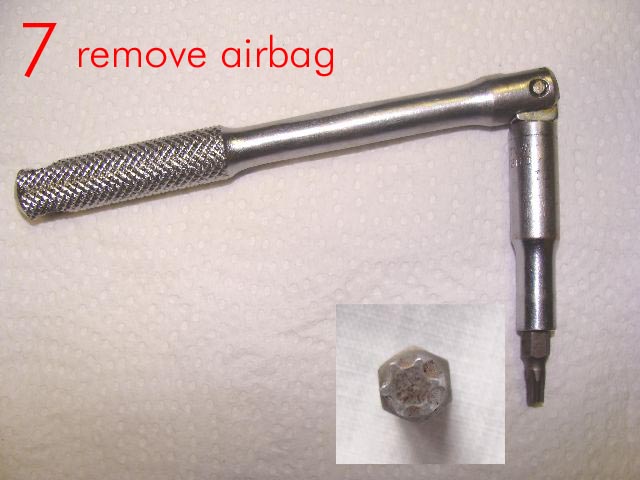
1 Remove the two air bag securing screws located on the underside of the steering wheel Located at 9 & 3 o'clock underside of steering wheel.
* Support the 'Air Bag Unit' while undoing these fixings as the air bag will move away from the steering wheel; as the screws are undone.
* Two sizes have been mentioned by different people, both 'koovin's' and mine are T30 Rods are T27 all 'Torx'(star) drive male bits, so make sure you find the correct size for your car, take care not to damage the screw head or you will never get them out!
2
Having completely removed these fixings
carefully lift the airbag off the steering wheel.
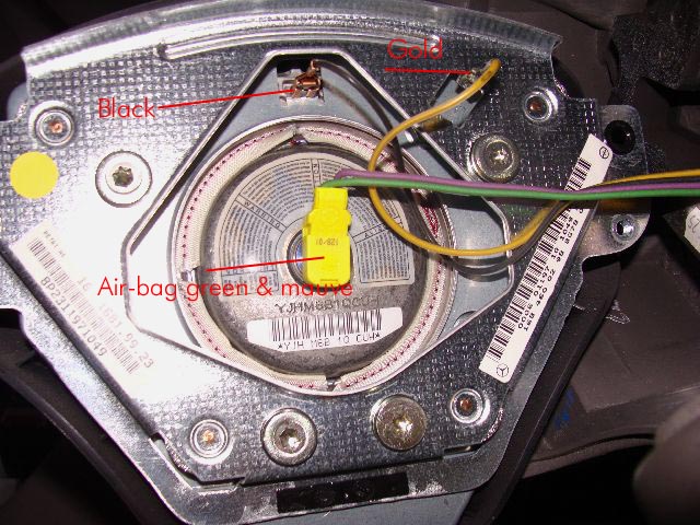
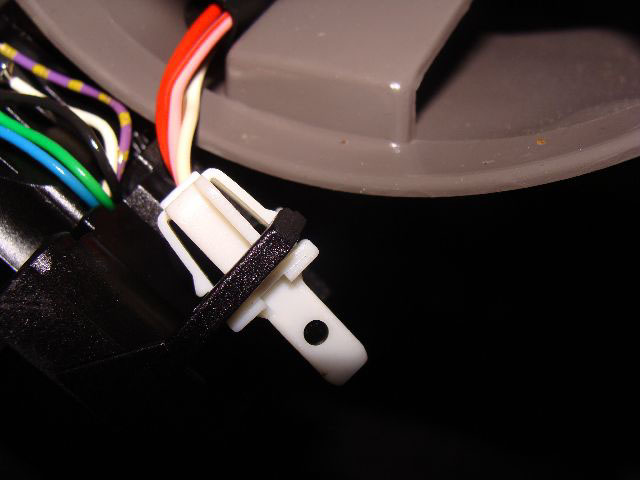
On the underside there is a central electrical connection. noting its position relative to the air bag unit this may be disconnected by gently levering away from the air bag with a flat bladed screw-driver, You will also have to remove the black and Gold wires, take care when removing the black wire connector.
I had problems and had to adjust the connector when replacing. It must be a good fit when replaced .
Note the difference in the design, the 2001 airbag in the left photo has the black & Gold wires attached to the air-bag
On the earlier models it appears they are attached to the horse shoe fitting forming part of the steering wheel.
Stow the air bag in a safe area positioned as to display the deployment area of the unit face up (store as situated when on steering column)
It must not be exposed to a temperatures of more than 100c.
* Note also the neat & tidy way the other wires are stowed, try to duplicate this when returning the Air bag unit.
* Having noted the position of the wiring connections/terminals connected to the air-bag or metal horse shoe, dependent on the year of A class you are working on. the wire in each case have different size spade connectors and so in theory cannot be replaced incorrectly, however confirm this is the case on your car before disconnecting.
If in doubt identify with a marker before disconnecting, or photograph if you have a digital camera.
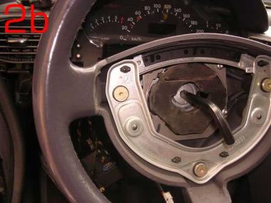 2b
2b Using a 10mm 'Allen' key remove the centre counter sunk screw.
This should be found tight and you must re-torqued to 80Nm on re-assembly.
I had to use the tools shown in photo marked 1 above to remove my steering wheel locking screw, there was no way it was going to move with just an Allen key now matter how it was extended. as shown in this donated photo. A torque wrench should be used to ensure the correct torque.
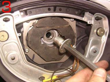 3
3It should be noted that due the the counter sunk screw being recessed an extension bar will be required complete with 10mm socket and 10mm hexagonal 'Allen' key. this method will prevent damage to the leather of the steering wheel.
Position your tools in such away as to avoid striking the windscreen when the screw gives (undoes).
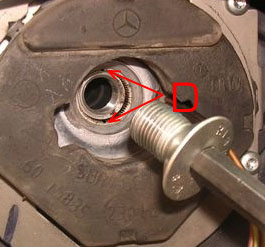
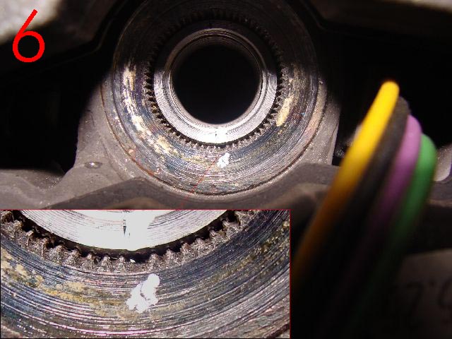
 Before removing the steering wheel, Note that at 12 and 6 o-clock, (top and bottom) on the spline centre of the steering wheel, there are two recess/markers, D these must be re-aligned with the arrows/markers on the steering shaft/column, on re-assembly thereby ensuring the steering wheel is relocated precisely as removed.
Do not remove the steering wheel until you have made yourself aware of these makers. see 6 above for detail
 8
8The steering wheel can now be removed, take care that any wiring are not pulled or stretched.
The clock spring will now be exposed.
This enlarged photo of the clock spring allows you to see the information on it . This should be followed or problems will arise when re-assembling.
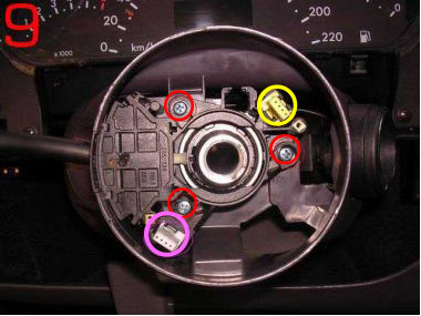
9. Removing the two ringed screws will allow you to remove the clock spring. F
10. When doing so lift the clock spring straight up DO NOT twist or the 8 (2 X 4) contact/pins on the underside will become damaged.
* Do not tamper with the clock spring once removed, failure to observe this rule may result in it having to be rewound or replace at great cost.
Steering Angle Sensor
As the information says the steering angle sensor is clipped to the back of the clock spring. Unless there is a diagnosed problem with this unit then do not separate the two components.
I am not going to claim that I know what this component does, or what influence it is failure will have on the car or indicator warning lights, but as it is name implies it does indicate to the car at any given time, whilst the ignition is on; at what angle the wheels are positioned relative to travel.
Owners have also had to have it replaced where the SRS (air bag) indicator has been illuminated and cannot be extinguished and well as where the ESP/ABS lights have lit, and cannot be deleted using the reset procedure. Its cost for replacement purposes is approx £250.00, plus of course fitting.
Note there are many things to check before replacing the unit.
11
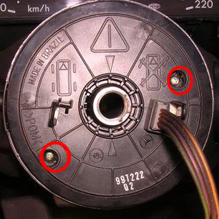
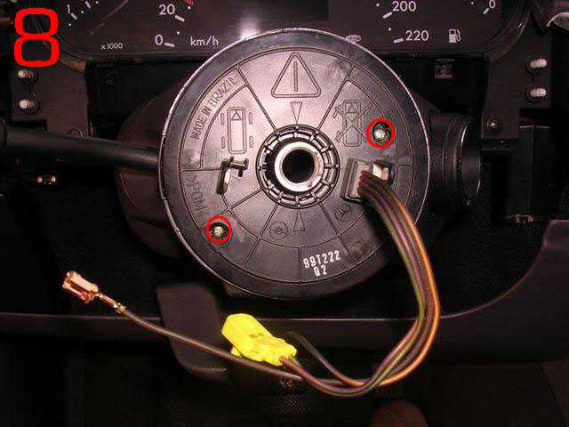
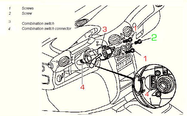
Removing the three ringed screws will allow you to remove the Combination Switch, the electrical connection should automatically unplug as it is removed.
Having lifted the switch you will now have to release the white 4 pin block which is secured to the switch, using a pair of pointed nosed pliers hold the two spring loaded securing clips in allowing the connector to be released from the old switch . It will clip back into place on the new or replaced switch .
12. When replacing push the switch firmly into position to ensure a firm fit.
13.
When replacing the clock-spring, small contact pins engage into the yellow & white 4 pin connecters. A & B therefore great care must be taken when replacing this component to ensure it is aligned and square to the steering wheel.
Note screw Numbered 2 (short screw) must be replaced in its original location or the steering lock may be damaged.(All 3 screws on my A160 2001 model were of the same length, to be safe simply replace the screws from where they were removed.
On completion of the repair
Re-assemble all components in reverse order paying attention to detail.
Re-torque the steering wheel locking screw to 80Nm)
Before reconnecting battery terminals turn the main lighting switch to dipped or main beam, this reduces the risk of the Engine management light staying on after the battery is connected. Where this does occur , the light can only be deleted using diagnostics equipment, pre 2001 cars this can only be done by MB or a MB independent garage.
* Re-connect the battery *On completing re-assembly
Ensuring that the correct procedures are followed you are advised to follow the above procedure by turning the light switch to 'side lights' prior to battery connection.
Connect Positive terminal first followed by the negative terminal * Remove wheel chocks.
* Turn on ignition.
* Check the operation of the combination switch, check:-
Indicators
Head light dip switch
Head light flasher
Indicators, left and right,
Front Screen wash
Front Wipers, Alternative wiper speeds. (Carry out this test on the now wet wind-screen.)
* Check Fanfare/horn
* Check and correct clock, mypage.35.
* Enter radio Code as necessary
* Reset electric windows where fitted (front & Rear.) See page 13
* Reset ABS/ESP See page 13 for procedures. This is best done while slowly moving the car.
* On road test ensure that the indicators cancel when straightening up after left and right hand turns.
(If this is faulty then the steering wheel has been incorrectly aligned)
*Note there are instances where following the disconnecting and subsequent re-connection of the battery the engine management light fails to extinguish on start up, where this happens, (I do not know why some cars are prone to this but believe that it is caused by the power surge hitting the ECU as the battery connections are made.) the ECU management light fault, can only be deleted using diagnostics equipment. This does not necessarily mean going to Mercedes-Benz, as many garages now use diagnostics equipment which is compatible with petrol cars produced for the EC from 2001, Diesels 2004 if your car was constructed before those dates you may have to visit a MB workshop or MB independent garage to get the light deleted using 'Star' Diagnostics equipment.
However if the lighting switch is turned to at least side lights prior to fitting the battery the spike of power/surge hitting the ECU will be reduced which should prevent this problem in the first place.
Having re-assembled the components parts, and connected the battery always test all services that have been affected by the job undertaken to confirm everything is working and safe.
I have not investigated this repair further but I suspect Mercedes-Bens Workshops would want your car for at least an hour, which would with Vat cost approx £110+ parts Plus they would want to put it on the diagnostics test prior to and following repair which for a short test would cost approx £60.00 plus Vat.
But please remember there are items that while doing this job you need to pay particular attention to. Correct torques for the steering wheel screw being just one, precise re-assembly of the steering wheel and components, clock spring etc, fail to get any of this 100% and you could finish up with more problems than you started and with and a large bill for putting it right by the garage. So please think about this before pulling your car apart.
I would like to thank 'koolvin' and also 'Raffa' both fellow owners of 'A' Class cars for their help in the production of this page, along with a number of the photographs.
As I have now had to replace the combination switch on my own car I have been able to contribute more detail and photos. Lofty
Continue if you wish to attempt a repair of your combination switch
So how is the switch stripped down to enable inspection and possible repair?
firstly ensure you have plenty of patience, ingenuity as a well lit working area.
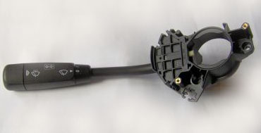
Take the switch apart:-
There are 3 main parts :-
(item 1 )The arm attached by wires to the (item 2 )switch body, and the securing section which locates on the steering column.(Item 3) If you look either side of the switch you will see a slide which is covered by a this plastic cover, break or carefully cut the cover away
.
You will now need a pair of pointed nose small pliers.
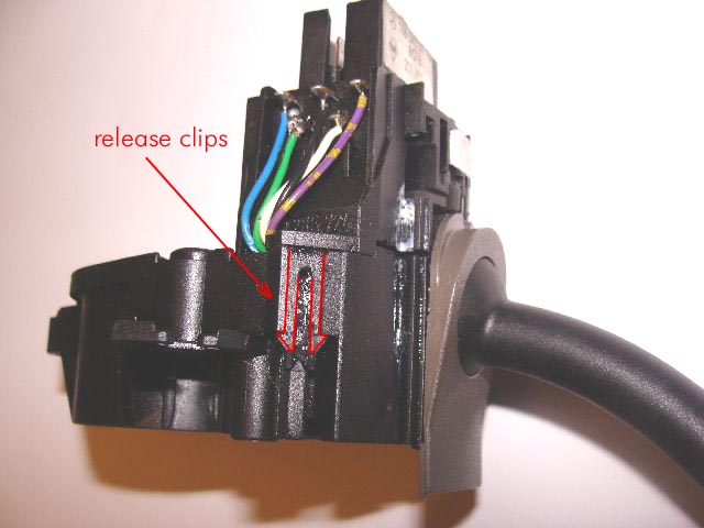
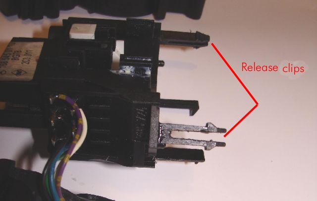 Look closely and you will see the clips, now exposed that hold the switch together.
Using the pliers squeezing the two parts of the clip together they will come into contact with the arrow head shaped plastic and will automatically open the switch an 1.8 of an inch or so, repeat the procedure on the other side of the switch body.
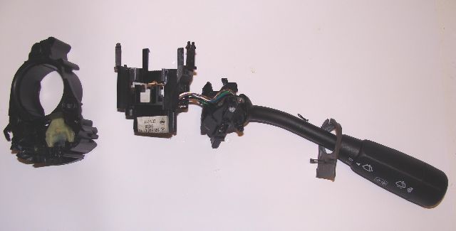
You should now be able to gently ease the switch sections apart
Take care not to break the wire /connections .
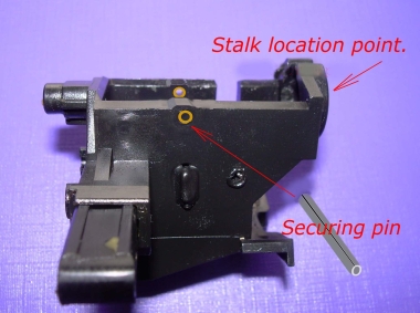
Because you will almost certainly find the securing pin shoulder/lugs broken, the arm section can be removed from the main body complete with securing pin.
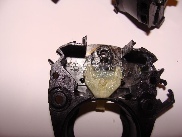
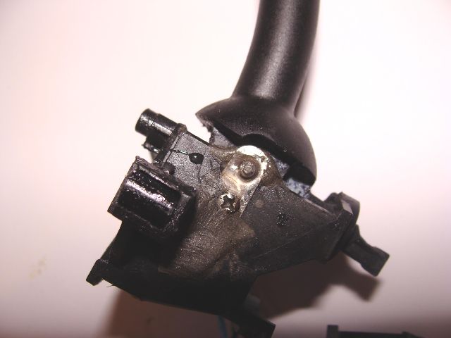 If the defect on the switch is the broken shoulders into which the pin should be secured, then they will need to be repaired. how you do this is entirely up to you but the holes MUST remain in the same location or the switch will not work when re-assembled.
As indicated above I finished up using metal salvaged from an old AA battery holder, to repair the shoulder both sides and secured them into place with a small self tapping screw, these had to be ground off flush on the inside or they would prevent fitting of the arm.
I also made up a longer pin so that it projected beyond the metal shoulders both sides, this I glued into place to prevent movement while in use, the pin being able to rotate in the arm, this is not the case with the original pin fitted.
Not pretty but very effective.
Although I am not going to strip out the new switch to test the repaired one, I am confident it will work if every replaced. Certainly if the opportunity arises I will test it on the car.
When re-assembling the repaired switch you will need to press the white plastic component in, to enable the components to house correctly.
This white lever is in fact the component part that returns the indicators to the off position after activation . Therefore if the problem is 'indicators fail to cancel' it could be this item which is broken.
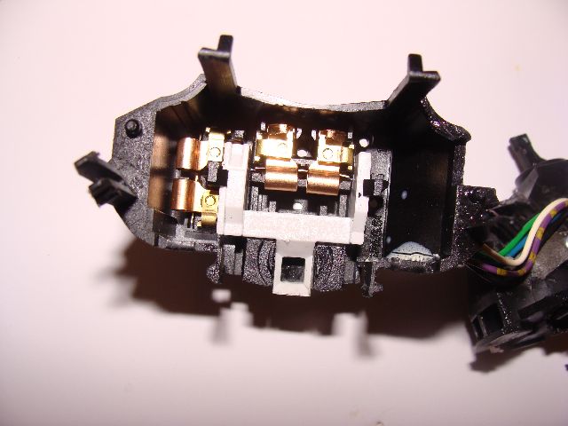 As previously mentioned if the fault is an electrical one and all wires are securely attached to the switch contact points, visually check the switch contact points there is every chance that one or more have burnt out. Either way a replacement switch will be required.
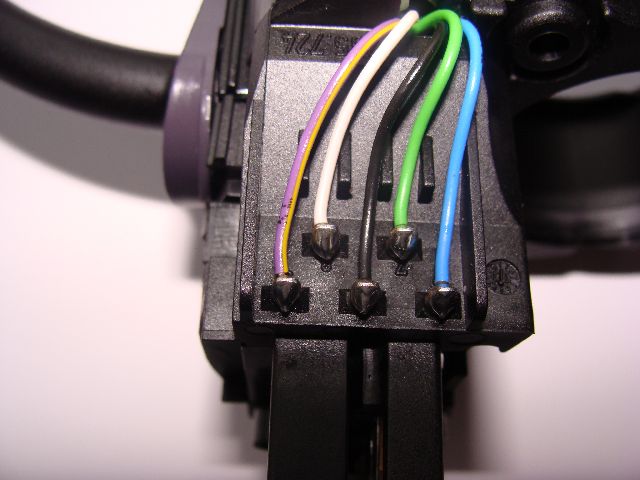
If you do have more than one wire detached , this will assist you in getting them soldered back to the right point of contact.
Do remember that using the car with a broken switch/faulty condition at night would be highly dangerous to other road users, even if the indicators and wipers were still working.
Arjan managed to repair his unit using the metal barrels cut from two electrical cable connectors which he placed into the remaining portion of the broken holes and then plastic welded them in place, this could be also attempted with a heat gun or glue gun, allowing adequate time for drying and curing before re-assembly.
There a number of instances where the arm has broken off I can't comment on how this happened.
What I do know is that the arm can get very stiff which may contribute to the problem, I therefore keep this point on my switch lubricated with silicone grease.
Removing/replacing Combination switch
For information in respect of accessing the combination for repair or replacement purposes please link to page mypage.70. and follow the procedures If you do not feel confident to undertake this task or you do not have the correct tools please refer to car to a garage for repair
The Procedure on page 70, only needs to be followed to the point where you can remove the switch.
If using a none Mercedes Garage It will pay you to obtain the combination switch switch first.
DO not expect a commercial garage to undertake repairs to the switch.
Always quote your Vin number when obtaining spare parts for your car.
Owners have indicated that they have managed to obtain the combination switch from car parts suppliers other than Mercedes Benz, I tried 3 good parts factors with out success. finally purchasing mine at Mercedes of Brighton Sussex. tel. 01273-707070 ask for parts.
Next.
Back to Index,
Purchase DVD.
Please Make a Donation.