I would like to thank Ed Hawkins for his input and some of the photographs on this page. It is as a result of his input that I have produced this page. Please note that I have not as yet had to carry out this procedure on my own car.
For information Ed's car is an X plate A160 with 38000 miles on the clock, a very low mileage for a car of that year, and yet he has still encountered problems with the swinging arm bushes.
Forethought on the part of DaimlerChrysler to fit a grease nipple during production, as was the case with the Austin/BMC Mini would have extended the life of the bearings, albeit even the Mini's suffered from problems on their swinging arms unless they were kept well serviced.
As the procedures for servicing these arms are the same for all 'A' Class models I am including it on my site.
Prevention is better than cure.
In the knowledge that the earlier 'A' class has suffered this problem I regularly spray the underside of my car including the swinging arms and sub frame with Duck oil purchased from Halfords Stores, this can be done quite easily while the under floor pans are lowered, this action so far has prevented any rust build up on any of the components under the car, and costs very little. I apply this with a spray attached to a small compressor but it can be done with a garden type spray, remember to wear a mask and carry out the procedure in open air.
NEVER WORK OR ALLOW OTHERS TO WORK UNDER A VEHICLE UNLESS PROPERLY SUPPORTED. THE JACK IS DESIGNED FOR RAISING AND LOWERING THE VEHICLE, AXLE STANDS CORRECTLY POSITIONED OR SIMILAR SUPPORT EQUIPEMENT MUST BE USED.
Please remember to implement ALL safety procedures as outlined on mypage.5.BEFORE STARTING WORK on you car.
As you will need to release the handbrake to carry out this repair ensure both front wheels are choked front and rear.
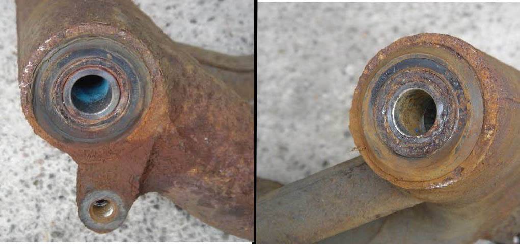
The symptoms of damaged/worn swinging arm bearings and shafts.
Signs and symptoms can be encountered in the following ways:- * Clonking noise from rear end:- when negotiating roundabouts, Uneven road surface, Speed humps
* Car wandering/stepping out on bends and roads with adverse camber.
* Uneven tyre wear
But Before jumping to any conclusions on the cause of the symptoms experienced:-
Check the springs for breakage. This a very common problem and can cause similar if not the same problems as the trailing arm bearings. There have now been several instances of both springs having been found broken . One owner's car recently failed it's MOT because both springs had been found on inspection to be fractured. It is very easy to inspect the springs while preparing to check the arms.
Check the wheel bearings
* Worn wheel bearings can also cause uneven tyre wear
* Jack up the rear wheel on the side you are working until the wheel is just off the ground
* Facing the wheel, grip the wheel top and bottom, and try to rock the wheel top out, bottom in (backwards & forwards). Do not use undue force.
*If there is play (movement) then this is a different problem and should not be confused with the swinging arm bearings.
* If no play is detected proceed to :-
Check the Trailing Arm Bearings
Inspecting the arm bearing for wear (play) for wear *Locate the car on a level standing
* Ensure the both front wheels are firmly chocked front and rear
* Slacken the wheel nuts of the wheel on the side you are working
* Jack the car up until the rear wheel just leaves the ground
* Remove the wheel
* Ensure the handbrake is in the OFF position
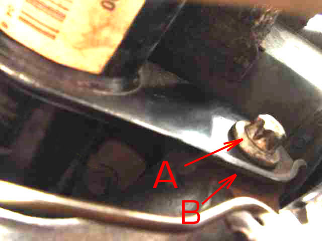
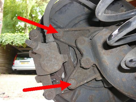
* Using the wheel hub and arm as a lever try to move the arm horizontally from side to side, do not use undue force, any play in the bearings, will located at point B
* The arm is secured to the rear sub frame by the 'Torx'(star drive) bolt A
* If the swinging arm bearings are sound you will not be able to detect sideways movement in either direction of more than 0ne millimetre (1mm) (Which is a very small amount of movement) Movement greater that this tolerance accompanied with unusual rear wheel tyre wear should be investigated further.
* In severe cases the bearing may heard to crack/click as the arm is moved from side to side.
Repair Options
If you intend undertaking this work yourself bear in mind that you will need a comprehensive range of tools which will need to include a
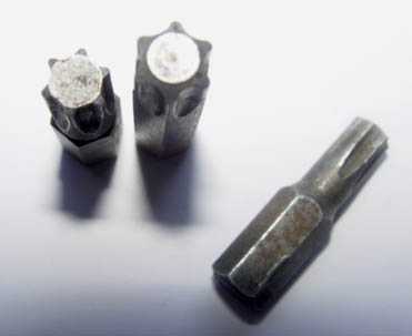
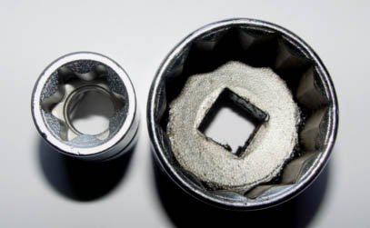 30mm hexagonal socket for the rear hub nut and an E20 'Torx' socket as well as 'Torx' bits (Star Drive)
NOTE to do this job professionally you do need a torque wrench, remember it is a dangerous to over tighten bolts, nuts etc as it is to not tighten enough.
Having got or obtained the required tools you now have two options for completing the task :-
Option 1
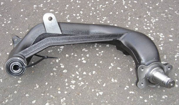 * Purchase new arms ready assembled with bearing pre fitted,
*Note the new bolts, (arms to sub frame) are not supplied as part of the New Arms.
* Although this option will cost more it is in my opinion the best option, as removing the old bearing from the existing arms can be problematic, fitting the new bearing and seals requires special tools if the job is to be done correctly.
Ed chose the first option and replaced his arms complete, looking at the condition of the existing arms a wise choice as I sure he would not have wanted to spend time cleaning and spraying the old units.
Parts required to Replace Arms.
option 1 * Left Arm part number A 168 350 3506 3406
* Right Arm Part number.A168 350 3606 3404
* Rear hub nuts X 2 part number A210 357 0172
* Torque bolts for control arm to sub frame X 2 Part number A168 357 0771
* Loc-tite
* Brake fluid for topping reservoir up( if you disconnect the hydraulic brake pipe.) for spec see page.28.
* If you decide to replace the coil springs while they are off the car Part number A168 320 0408 applies.
*New pattern springs are available however the hole in the cast iron arm central to the spring base will need to be blanked using Rubber grommet, part number A168 997 0686 (For further details see mypage.25.)
*Clean cloth or wipes to hand
For those of us that may wish to limit the cost of repairing these units and already have the necessary tools, you can service your own swinging arms using repair kits, available through MB parts.
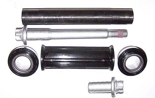
Option 2 Refurbish Existing Arms One kit required for each side.
 * Note. Each repair kit includes the 2 x bearings and 2 x seals plus torque bolt securing the arm to the sub frame) The plastic and metal sleeves have are not included and have to be purchased in addition. Special tools may be required for fitting.
( Removing the arms when undertaking a repair to the original arms, the hubs do not have to be stripped.)
Parts required for option 2 *Standard Repair Kit's A160 981 0518
* 1 x plastic sleeve part number A168 357 0148
* 1 x metal sleeve part number A160 357 0248
This mail was received from Clive a fellow owner with some advise when using a 'repair kit' to replace the swinging arm bearings. w
Hi Lofty, Just to say thank you for creating this excellent resource and to add a few tips that other owners might find useful when changing the rear swinging arm bearings:
I've just completed this job and went down the bearing kit route.
The tips I would offer are:
1. When inserting the new bearings kit firstly insert the plastic sleeve as it has to sit inside the ridge. It can be done after fitting one of the seals and bearing races but it is a bit fiddly.
2. If you manage to dislodge the bearings from the plastic carrier be careful when putting them back in as they are NOT rectangular.
They are infact very slightly tapered and go in with the narrow end towards the narrow end of the inner race.
I had some in the wrong way round and of course the bearing wouldn't seat properly and felt very rough and lumpy when turned.
Just a couple of tips that might save some head scratching.
Keep up the good work.
Regards
Clive Thanks Clive very useful information.
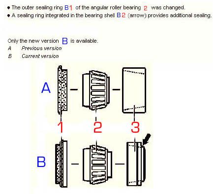
You also need to be aware that there has been a modification to the replacement bearing kit, pay attention the re-assembly of the bearing and seal within the arms.
 Summary of Procedure
* Remove Road wheel
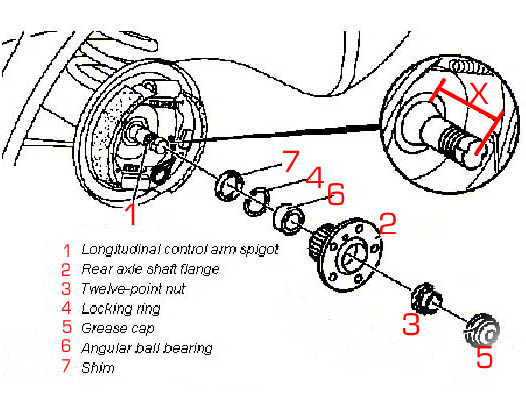
* Remove centre grease cap 3
* Refit Road wheel,(Do not torque nuts)
* lower to car to the ground
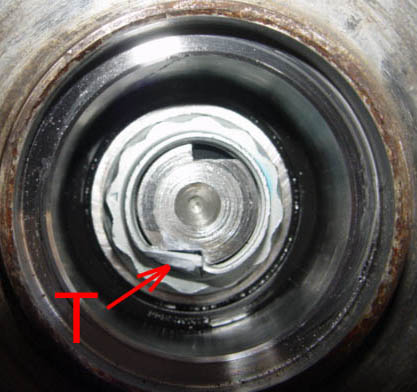 *Using a suitable tool, unlock the hub nut locking tab T
* Slacken the 30mm rear hub nut do not remove at this point
* Raise the car until the wheel just clears the ground
* You will find it necessary to release the middle and rear under floor panels to get axle stands under the sub frame cross member.14
* Be sure to take every precaution to ensure the car is stable and safe before attempting to work under the car.
* Remove wheel
* Remove grub screw in brake drum 2 T30 bit
* Ensure the handbrake is fully OFF
* Remove brake drum 1( tap the drum with a hammer, rotate the drum while doing so, this will assist with the removal.)
* If the brake drum will not come off it may be necessary to slacken the auto adjuster on the handbrake, this is situated within the drum and is accessed through any one of the bolt holes which is aligned with the adjuster as the brake drum is turned.
* Having removed the drum take great care not to contaminate the brake shoes
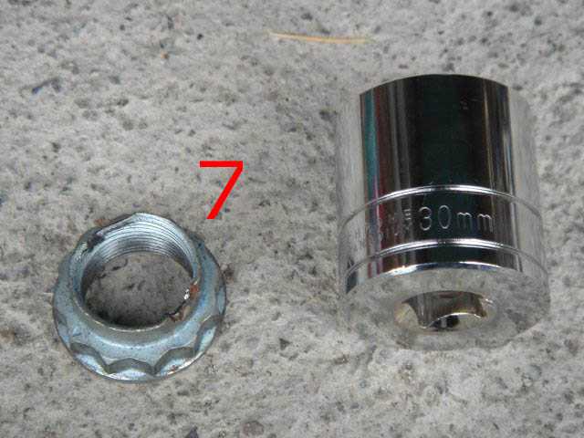
* Remove the previously slackened Hub Nut 7
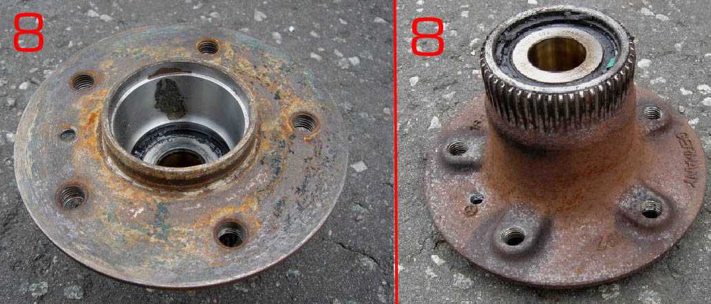
Withdraw/Remove the hub from the stub axle. 8 (
If this is found to be tight and will not come off.
* Using the spare steel wheel fit the wheel to the hub flange, using the bolts provided with the steel wheel secure the wheel to the flange screw all 5 wheel bolts into the flange evenly but do not tighten the wheel, this can now be used as a improvised puller to shock the flange into coming away from the axle spigot, In extreme cases a puller may be required)
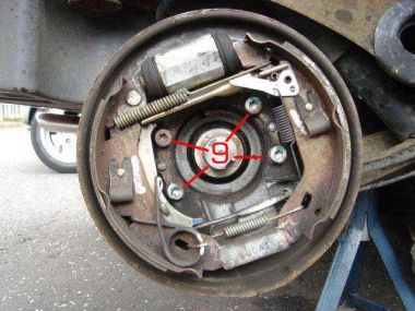
* Remove the 4 bolts 9 holding the back plate to the arm
* Remove the back plate complete with brake shoes assembled and handbrake cable left in situ 11 do not kink or bend the brake cable or outer casing or damage will be caused.
**Optional
Ed managed to remove the back plate complete with the Speed sensor, the brake pipe and the parking brake cable left attached, IF you opt to do this take extreme care not to damage or bend the brake pipe, or pull the wires from the ABS/ESP connector . In all three cases there is sufficient cable etc when the clip and ties are removed but take extra care.
For my part I would follow the guidance of MB, I leave you to make your own decision! Removing both the speed sensor and brake pipe does create more work but the component parts are less likely to get damaged whilst working on, and removing the trailing arm.
**
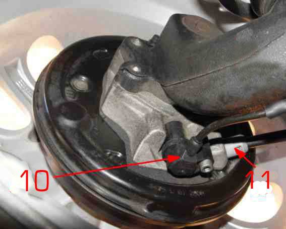
* Remove the ESP/ABS (T30 'Torx' bit)(speed sensor) by removing the retaining bolt. Secure the speed sensor & cable in such a way as to afford them protection against damage.10
*** Remove the cap of the master cylinder(Brake reservoir) Place a thin piece of polythene over the opening, refit the cap tighten firmly. (this action on your part will reduce/stop the flow of brake fluid from the brake pipe when it is removed from the wheel cylinder)
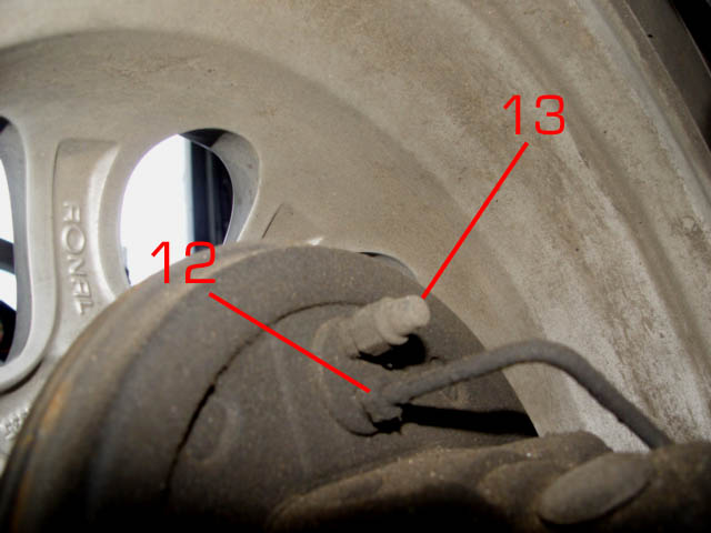
*** Remove the brake pipe-coupling from the wheel cylinder 12 situated at the top and rear of the back plate. 11mm* Do this with caution ensuring that the collar/nut revolves on the pipe as it is turned and that the pipe its self does not twist with the collar/nut. If necessary spray with WD40 before attempting it's removal.
Should the pipe twist with the collar the pipe will need to be replaced.
* Take care not to shear off the bleed valve situated above. 13
* Where available fit a female blanking plug onto the metal brake pipe to further reduce brake fluid loss.
12
* You may find it necessary to slacken the fixings of the plastic wheel arch liner this will give you more flexibility to get at the various bolts etc.
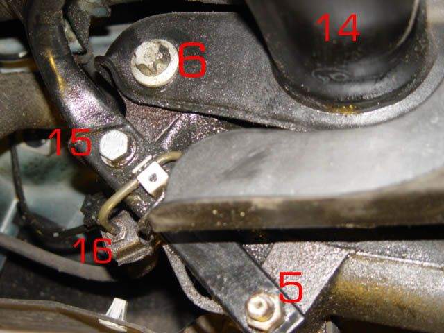 * Remove lower shock absorber bolt which also secures the lower end of the torsion bar.( 18mm x 2)5
 * Remove the brake hose, Speed sensor from any securing clips.
* Manually push the control arm down to enable removal of coil spring. 4
* If original springs are fitted, remove rubber dome and metal cap from swinging arm
* Remove anti roll-bar bolt 15 16mm (observe the positioning of the brake pipe and assembly and spacer.(where available use your digital camera to record the location, positioning of the various cables, hose & pipes. These can be invaluable when re-assembling)or of course you can use this sites photographs as your reference)
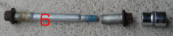
* Remove the trailing arm mounting bolt, E20 6 '"Torx' socket(star drive) holding the arm to the rear sub frame support the arm while doing so, or damage may be caused to surrounding components.
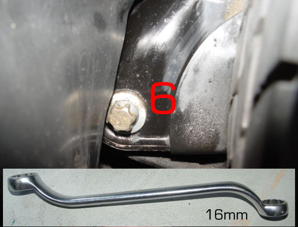 * Hold the outside end of the bolt with a 16mm ring spanner. (The bolt head is star drive but the 16mm ring is a good fit.)
* Carefully remove the swinging arm, have extreme regard for the brake pipes etc
* Compare the old arm removed with the New arm. Note that a spacer was fitted with the old arm THIS IS NOT REQUIRED WHEN FITTING THE NEW ARM.
* Re fit New Arm, you may need the assistance of a helper or second jack to position and align the arm to enable the fitting of the bolt.
* Replace all components in the reverse order.
* If using old bolts, clean off all old Loc-tite, apply fresh before re-fitting
* Use Loc-tite on all threads accept wheel bolts & Wheel Hub nut
* Re-torque all nuts & bolts as directed.
* If fitting the modified coil springs, the rubber and metal cap that sit on the location pinnacle on the swinging arm are not re-fitted/required.
However the hole in the swinging arm, centre to the spring base should be fitted with a rubber grommet part numberA168 997 0686
If these grommets are firmly in place then moisture will be prevented from entering the trailing arm, this could assist in maintaining the trailing arm bearings in good order.
* If installing original springs, with rubber & metal caps, ensure these are all in a sound condition
* Re-fit the speed sensor
* Re-fit the brake pipe
* Bleed brake wheel cylinder, using bleed valve 13 connect a tube to bleed valve ensuring the end is below the fluid in a jar. (For more detail see My page 28
* Remove the polythene from the top of the brake master cylinder reservoir.
* Open the bleed valve and get an assistant to press the brake pedal a couple of times, or until the air bubbles cease to flow from the tube, Close the bleed valve firmly do not over tighten. replace protective cover on bleed valve.
* Re-fit wheel & bolts
* Lower car
* Torque the hub nut It is vital that a torque wrench is used to achieve the correct degree of tightness.
*Using a suitable tool lock the tab T on the stub axle hub nuts when complete (MB have only locked one tab on each of the hub nuts my car, what is good enough for them during manufacture is good enough for me.
This also means the wheel hub can be removed and reused for the second time with out replacing the nut, as the unused tab can be used) Where both tabs have been previously used, fit new nuts.
* Remove the wheel
*Replace the grease cap on the hub, Ensure this is square with the hub , tap on the rim of the cap ensuring the cap is fitted evenly into the hub, if this has been damaged during removal it must be replaced.
* Re-fit wheel, (A small amount of grease on the threads of wheel bolts will ensure they tighten evenly
* Torque the wheel bolts
* Having completed the task, Test Hand Brake, Foot Brake, if satisfactory, Road Test
* Enter record of work carried out in your service history file
Re-Furbishing Existing Arms If you are using the repair kit method the wheel hub can be left assembled. However the ABS/ESP (speed sensor) along with the brake fluid pipe will still need to be disconnected and clips removed.
* In addition the left or right parking brake cable will need to be disconnected before the arm is released.
* This is best done at the point where the left and right hand cables join the main hand brake cable, Ie forwards to the sub frame cross member.
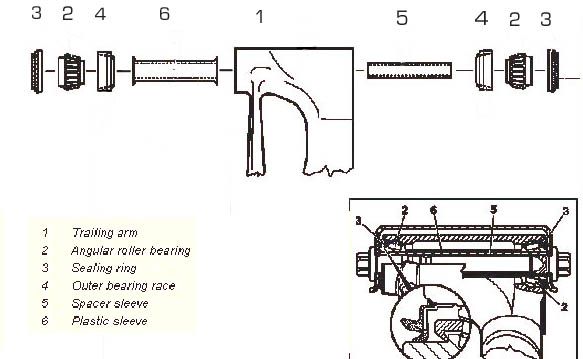
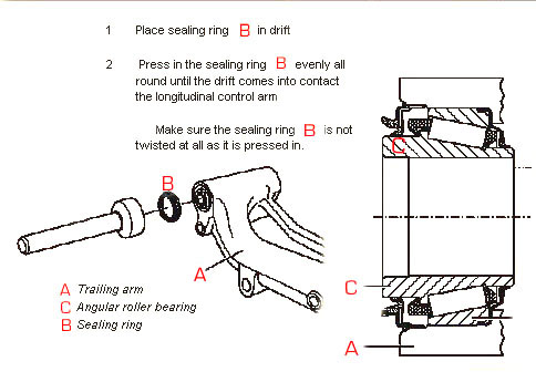 * Having removed the arm complete with hub the bearings and seals can be removed and replaced on the workshop bench.
* The diagram shows that MB use a drift to site/fit the outer seals into the arm. I find that the back of a suitable size socket will do the same job , however it is vital to get the seal square with the recess in the arm before tapping firmly in behind the bearing casing.
* Remember it is this seal the stops the ingress of water and moister into the bearing chamber. It must be fitted correctly as well as remain undamaged to achieve this.
* Make sure the parking brake cable or outer casing does not become damaged while working on the bearings.* Observe all of the other features mentioned in the above section.
Torque Settings.
* Control arm to sub frame 110Nm 90 degrees
* Torsion bar to trailing arm and shock absorber 1st stage 80Nm
* Torsion bar to trailing arm 70Nm
* lower shock absorber mounting bolts 80Nm
* Rear hub nut 150Nm.
* Speed sensor bolt 8Nm
* Brake pipe to wheel cylinder 14Nm
* Back plate to longitudinal arm 35Nm
* Wheel bolts110Nm
Wheel Bearing replacement
Wheel bearing problems are usually detected by a low rumble as the wheel is slowly spun, or anything up to a high pitch whistle at speed. As with the trailing arm bearings in severe cases the bearing within the hub may be heard to crack as the wheel is turned. Severely worn bearings will affect the wear on the tyre tread, more usually causing wear on the inside edge of the tyre.
 * To replace the bearing follow all the procedures as far as removing the wheel hub in the text above. (Replacing/repairing trailing arms)
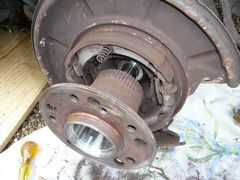
* The bearing is located within the hub/flange. 2
* To replace the bearing follow all the procedures as far as removing the wheel hub in the text above. (Replacing/repairing trailing arms)
* The bearing is located within the hub/flange. 2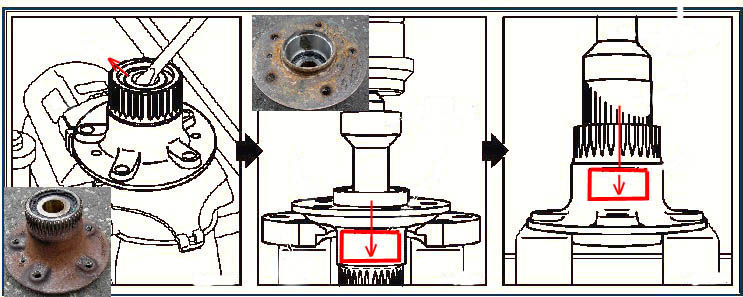
* While working on the flange take precautions not to damage the spline on the outside of the flange, this is the mechanics that provides the speed sensor ESP/ABS information.
*Having removed the flange if possible clamp it in a vice, Protect the spline.
* With the flange laying on the disc of the flange remove the spacer & retaining clip.
*Lever out the bearing inner using a suitable screw driver
* Press out the outer race of the bearing from the flange side, using a suitable drift.
*In the Mercedes-Benz workshops a special drift would be used the re-position the new bearing and seal.
* In the DIY field it is normal to use the flat site of suitable sized socket ensuring the bearing is driven in to the flange square with the bearing recess until it finally reaches the stop.
*Note When working on the wheel flange/ hub remember you are working on cast iron, when driving home bearings seals etc ,ensure the flange is fully supported at all times.
*NOTE If the longitudinal control arm spigot is 62.5mm in length measured from the front end of the contact surface of the spigot X (in above diagram,) a shim of approx. 4mm in size must be used
* Replace the shim & New 'C' Clip
* Having replaced the bearing and component parts, follow all re-installation procedures as for the trailing arm.
*Please note that this another job which I have been fortunate enough not to have to carry out. All I can say is that they are not normally difficult and are well within the scope of the average DIYer.
* The part number for the bearing kit on model specifically covered is A168 350 0435
However be aware that there are two kits, so please ensure you provide your own vehicle Vin number when ordering/purchasing spare parts, that way you can be assured of getting the correct spares
* I for my part will always purchase DaimlerChrysler Mercedes-Benz parts, from my experience they are not a lot more expensive and you are assured that they are correct parts for your vehicle.
If your vehicle is fitted with disc brakes at the rear please refer to this document for details as to how to remove this calliper disc and hub/flange.
This information and Photos were contributed by a fellow owner, thanks Peter
Remove wheel
Lever off hub nut cover. Remember you are going to replace this item, ease it slowly and evenly from the hub.
Undo the locking tab on Hub nut, if both tabs have been used new nut's should be fitted
Remove Hub nut (30mm socket)
Remove grub screw (Torx 30)
Handbrake off.
Now proceed as follows:-
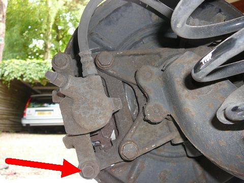
Undo lower Guide pin bolt
Swing central part of brake assembly upwards
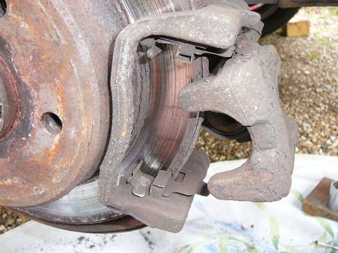 Remove the brake pad nearest to you by levering it towards you.
(You may not need to do this if your discs are not worn)
Remove the brake pad nearest to you by levering it towards you.
(You may not need to do this if your discs are not worn)The other pad can remain in situ as we now have enough room to slide the calliper away from the disc.
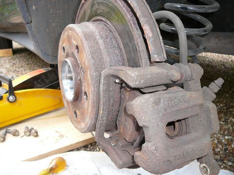
Prepare piece of wire to support callipers
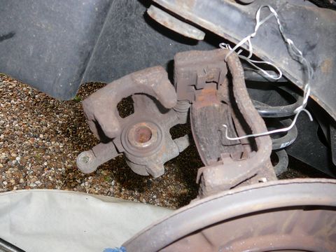
Undo calliper bolts and suspend calliper from wire
Now we come to the fiddly bit!:-
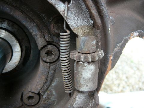
Inside the disc is a drum holding the hand brake pads.
The pads maybe too tight to the drum to allow easy removal without first slackening off the adjuster.
You can do this through one of the wheel bolt holes. So that you know what you are trying to do here is a picture of the hand brake assembly on the LH wheel
 Rotate wheel so that a hole is in the 2 o'clock position LH wheel (10 o'clock RH wheel)
Look for the adjusting wheel and turn it with a screwdriver.
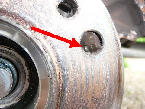 In order to loosen the brake pads move it as follows :-
For the LH wheel move the teeth from the front of the car to the rear of the car.
For the RH wheel move the adjusting wheel's teeth from the rear of the car to the front.
 Gently tap the brake disc assembly while rotating then pull off
 Disc will come off and then you can pull off the hub, or they might come off together.
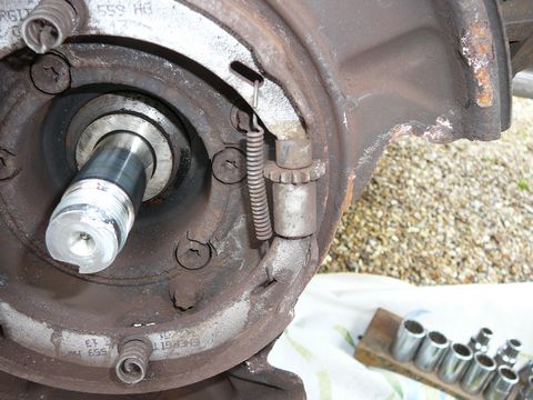
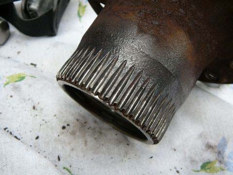 The ESP/ABS transmitter (Spline) cleans up nicely>
Re-assemble in reverse order remembering to re-adjust the hand brake adjuster, DO NOT OVER TIGHTEN.
With the handbrake off you should be able to turn the disc by hand
With the hand brake fully on you should not be able to turn the disc even when the wheel is re-fitted.
Next.
Back to Index,
Purchase DVD.
Please Make a Donation.